
TWO ROLLER MACHINE (Twin Disk Type) | 미끄럼구름 제어형 | 기어변속기철도휠압연롤러 시험기
Two Roller Machine 은
- 롤링–슬라이딩 접촉 피로(Rolling–Sliding Contact Fatigue)
- Traction (견인력) 특성 평가 분야에 사용되며,
- 흔히 Twin Disk 시험기로도 지칭 됩니다.
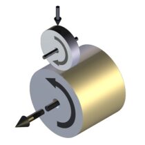
Two Roller Machine 타입 선접촉 시험기는
- 기어, 감속기, 압연롤러, 롤러베어링, 철도레일의 소재와 윤활유의
- 미끄럼 구름 접촉 제어형 (SRR=Slide roll ratio Controlled) 마찰마모윤활 시험기 일 뿐 아니라,
- 순수 구름접촉피로 시험도 할 수 있습니다. (참고 : 구름접촉피로 RCF 전용시험기는 별도로 있습니다.)
- 모델 TE 74H는 최대 30kN 하중 적용 가능.
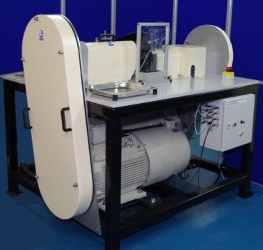
영국 PHOENIX TRIBOLOGY사 제조
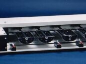
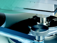
모델 TE74 TWO ROLLER MACHINE
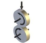
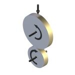
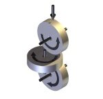
Two Roller Machine (Twin Disk Type) 마찰마모윤활 시험기의
시험 형상 이미지
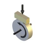
모델 TE 53에만 적용 – Block on Ring 전용 시험장치
모델 TE 73에만 적용 – 토로이달 변속기(Toroidal CVT) 시험장치
TE 72에만 적용 – 압연롤러 시험장치 – 하부롤러 X축 변위 이동제어
시험 대상 샘플과 분석 요소 :
- Cam shaft materials (캠 샤프 재질)
- Contact resistance measurement (접촉 저항 측정을 통한 윤활막 형성과 윤활막 파괴현상 측정)
- Delamination wear (박리 마모)
- Elastohydrodynamic lubrication (탄성유체 윤활)
- Gear lubricants (기어 윤활유 특성, 감속기 윤활유 특성)
- Gear materials (기어, 감속기 재질)
- gear surface treatments (기어 표면 처리)
- Hertzian contact (헤르쯔 응력 피로 시험)
- hypoid gear lubricants (차동기어 윤활 특성)
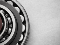
- journal bearing(저어널 베어링 시험)
- Pitting(피팅-피로 부식 마모)
- Rolling contact fatigue(구름 접촉 피로도 시험)
- Rolling mill(압연 구름 롤러)
- Scuffing(스커핑-기어의 Seizure(늘어붙음) 현상)
- Smearing(스미어링-굴림기어의 Seizure(늘어붙음) 현상)
- Slide/roll (미끄럼/구름 접촉 비율 제어)
- Traction coefficient (견인 마찰계수)
- White etching layers(표면에 급가속 급정지 등의 피로가 누적 되어 발생 되는 층)
영국 PHOENIX TRIBOLOGY사 TWO ROLLER MACHINE
-선접촉 타입-견인력 시험기 -미끄럼 구름 비율 제어형(SRR)
-모델별 특징 차이 설명
모델 TE 54 : (최대 하중 500N)
-기어 윤활제 및 구름 롤링 유체를 사용한 기본 마찰 견인(=Traction) 계수 테스트.
-MTM(=Mini Traction Machine)
-롤러를 축에 지지하는 방법 : Over Hung Roller 타입
-유명 사용자 리스트 : Honda R&D / Kobe Steel /Kyodo Yushi /Tonen General Sekiyu /Tohoku University /University of Sheffield
모델 TE 72S : (최대 하중 5 kN)
모델 TE 72H: (최대 하중 21kN)
-레일 vs 휠, 압연롤러 등의 마찰 견인력(=Traction) 제어 제품에 대한 모델링.
-롤링 유체에(=Rolling Fluid)에 대한 테스트.
-압연 롤러 공정의 다양한 SRR(Slide Roll Ratio)제어에 대한 Master/Slave 제어 기법 →매우정밀한 속도차를 실시간 편하게 Slip 제어 가능.
-TE 72/HIS 트랜지스터 유도 가열 시스템 (옵션)
이 시스템은 대형 테스트 롤러에 국부적인 가열을 제공하며, 일반적으로 냉각 유체 제트와 함께 사용됩니다. 따라서 롤러가 주기적으로 가열 및 냉각되는 강철 압연 공정 모델링에 적합합니다.
-에너지 절약형 파워 제어 시스템 (Circulating Power System) : 한쪽 모터가 발전기처럼
작동하면 → 그 전력이 DC 링크를 통해 → 반대편 모터로 전달됨, 두 모터가 전력을 서로 주고받는 재순환 구조
-축간 거리 가변 조절형 구조 : Variable Shaft Center Distance (테스트 롤러 직경 선택에 있어 최대한의 유연성을 제공)
-Skew Angle : +/-3 degree
-Axial Travel : 30mm
-롤러를 축에 지지하는 방법 : Over Hung Roller 타입
-유명 사용자 리스트 : LB Foster Rail Technologies(미국 NASDAQ 상장 철도 인프라 전문기업), Beijing Technical University, Tsinghua University, Arcelormittal Maizieres, Tata Steel, Tonen Steel, Jiangyin Steel, Kobe Steel
모델 TE 73H : (최대 하중 21kN)
-견인 유체 평가. 토로이달 변속기 모델링 (=Toroidal Transmissions).
-롤러 사이에 3번째 디스크 삽입 가능
- → 접촉면에 velocity gradient 발생(같은 접촉면 안에서 위치에 따라 속도가 조금씩 달라지는 현상)
- → Spin effect 연구 가능
- → CVT(무단변속기) 조건 모사 가능
-레일-휠 인터페이스 모델링(Rail-Wheel Interfacing).
-레일 견인력 제어 제품 평가
-롤러를 축에 지지하는 방법 : Over Hung Roller 타입
-유명 사용자 리스트 : Escola Politecnica da Universidade de Sao Paulo/Fiat Research/Mitsubishi Oil/NTN Bearings/Torotrak Ltd/Exxon Chemical & Engineering Co/Findett Corporation/LB Foster Rail Technologies
모델 TE 74S (최대하중 12kN) :
-기어 윤활유를 사용한 마찰력 견인 계수 테스트.
-롤러를 축에 지지하는 방법 : Fully Supported Roller 타입
모델 TE 74H (최대하중 30kN) :
-기어 윤활유를 사용한 마찰력 견인 계수 테스트.
-고속 기어의 스커핑 모델링.
-기어 소재 재료 테스트(고하중 고토크 시험장치가 필요)
-롤러를 축에 지지하는 방법 : Fully Supported Roller 타입
-유명 사용자 리스트 : CETIM(France) / PSA(France)/ SNECMA(France)/IST Fraunhoffer Braunschweig(Germany)/IIT Patna(India)/KITECH(Korea)/Southampton University(UK)/
DANA Corporation(USA)/Timken(USA)
PHOENIX TRIBOLOGY사 TWO ROLLER MACHINE 상세 정보–> 링크
Over-hung 타입 :
- 롤러가 축의 끝(shaft end) 에 장착되어 있고, 한쪽만 지지됩니다.
- 말 그대로 캔틸레버(외팔보) 형태입니다.
- 특징 : 롤러 탈착이 비교적 쉬움. 축 분해 없이 롤러만 빼고 교체 가능.
Fully Supported 타입 :
- 롤러가 축의 중앙에 위치, 양쪽에 베어링으로 지지됩니다.
- 축 끝이 아닌 베어링 사이에 롤러가 장착되는 구조입니다.
- 특징 : 높은 하중 용량 → 축이 양쪽 베어링으로 받쳐지기 때문에 더 큰 접촉 하중을 견딜 수 있음.
SCUFFING(스커핑) 의 의미 :
1.SEIZURE 라고도 한다. 베어링 등의 습동부에서는 윤활유가 부족하게 되면 마찰면이 용착하여 면이 거칠어지는 경우가 있으며, 극단적인 경우에는 고착하는 수도 있다. 이 현상을 늘어붙음이라고 한다. 기어의 늘어붙음은 스커핑(scuffing), 굴림기어의 늘어붙음은 스미어링(smearing)이라고 한다. 늘어붙음은 윤활유 부족에 의하여 기름막이 찢어지기 때문에 생기는 현상이다. 특히, 같은 종류의 금속을 마찰시키면 늘어붙음이 쉽게 일어나므로 습동부에 같은 종류의 금속을 사용하는 것은 피하는 것이 좋다.
2.높은 압력으로 접촉하여 통상 오일로 윤활하고 있는 금속 표면의 국부적인 융착에 의하여 발생되는 상처로서, 스코어링(scoring)이라고도 한다.
일반적으로 엔진의 피스톤 주위나 캠에서 볼 수 있는 상처를 스커핑, 기어에 의해서 발생하는 상처를 스코어링이라고 한다.
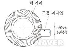
HYPOID GEAR(하이포이드 기어);
차동 기어의 일종으로, 테이퍼 롤러 베어링에 지지된 구동 피니언 기어는 링 기어의 중심보다 낮게 설치되어 있는 스파이럴 기어(spiral gear) 형식이다.
피니언 기어를 크게 제작할 수 있어 접촉률이 크고 원활하게 회전하여 감속비도 크게 할 수 있는 장점이 있다. 또한 피니언 기어 위치를 낮출 수 있어 프로펠러 샤프트(추진축) 위치와 차체의 지상고도 낮출 수 있다.
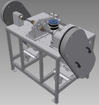
General Description:
The TE 74 Two Roller Machine is for the study of traction, wear and rolling contact fatigue under conditions of heavily loaded, lubricated, pure rolling and rolling and sliding. The machine incorporates two motors, one to provide the input power and one to absorb the transmitted power.
To achieve the necessary high loads with small diameter rollers, hence high contact pressures, the test rollers our mounted on shafts with bearings on either side, in the “fully supported” configuration. As a consequence, spindle bearings are exposed to, and must run in, the test lubricant.
To achieve satisfactory performance in line contact, the mounting/loading arrangement has adjustable alignment, with the upper specimen shaft carried on a pivoted arm and with a spherical bearing incorporated in the pivot axle. Axial alignment is achieved by indexing the pivot axle. Loading is achieved by means of a servo controlled pneumatic bellows actuator with force transducer feedback.
The lower specimen shaft is carried in fixed bearings. The drive to the lower roller incorporates an in-line torque transducer for measuring the input torque to the system. It should be noted that the traction measurement is thus subject to parasitic losses associated with the roller spindle bearings. These losses are small but may be quantified by running the unit under conditions of zero slip at different speeds and temperatures.
A vibration sensor is provided for detecting surface failure. The upper roller housing is electrically insulated and slip rings are provided on the roller shafts for electrical contact resistance measurement.
A lubricant service module is fitted as standard incorporating a sump tank with immersion heater, delivery pump, scavenge pump and oil to water heat exchangers for cooling.
The motors are a.c. and powered by conventional vector drives allowing precise control of speed. Power is re-circulated electrically via a common d.c. link between the drives, upstream of the frequency inverter stages. Total power requirement is thus limited to the system losses. For control purposes, one drive is designated as master with the second drive deriving its speed set point, adjusted for the required slip ratio, from the master drive.
Design Variants:
Two versions of the machine are available. The TE 74S (standard capacity) incorporates two 5.5 kW motors, a shaft centre distance of 40 mm and 12 kN loading system, whereas the TE 74H (high capacity) has two 30 kW motors, a shaft centre distance of 70 mm and 30 kN loading system.
Drive Configuration:
The lower roller spindle is connected to an in-line torque transducer via a cardan shaft; the transducer is connected to a lay shaft by a coupling and the lay shaft connected to the motor by pulley and timing belt. The upper roller spindle is connected to a lay shaft by a cardan shaft and the lay shaft connected to its motor by pulley and belt drive.
Control and Data Acquisition:
The TE 74 has PC based sequence programmable control and data acquisition. This is provided by an integrated Serial Link Interface Module and COMPEND 2000 software running on a host PC, operating under Windows. Data is stored to hard disc in standard spread sheet compatible file formats (.csv or .tsv).
Tests are defined by a sequence of steps, each step containing set-point, data recording rates and alarm level information. Set-points may be adjusted by step change or ramp. The test sequence is followed unless interrupted by the operator or an alarm. Set-points may also be adjusted manually using on screen toggles.
Controlled Parameters:
Motor speed
Motor speed difference–>(두개의 롤러 각각에 대하여, 미끄럼/구름 비율 PC에 의한 자동제어 가능)
Applied load
Test fluid temperature
Test duration
Measured Parameters
Motor speed
Motor speed difference
Applied load
Transmitted torque
Lubricant inlet temperature
Test bath outlet temperature
Vibration sensor output
Electrical contact resistance
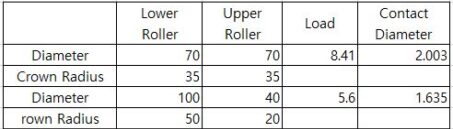
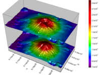
모델 TE74 기어 피로 시험기의 표준버전과 고하중 버전의 접촉압력 차이
Operating Envelope – TE 74S(표준버전, 최대 12kN 하중):
Characteristic showing motor torque-speed characteristic (available torque) compared with roller generated torque, assuming traction coefficient of 0.1, with corresponding reduction in applied load. Note that the full load can be applied at full speed in pure rolling or under conditions where the traction coefficient is less than 0.08. 기본 샘플 롤러 표준 40mm on 40mm 사양하고, 두개의 롤러 직경 총합이 80mm 이하 사용. 최대 차이는 15 on 65mm.
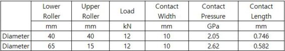
Flat Rollers5 mm contact width
Crowned Rollers 4 GPa Contact Pressure
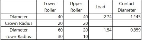
Note that as the minimum specimen diameter is 15 mm, a diameter of greater than this is required for a crowned roller sample machined on a 15 mm shaft. The practical minimum diameter for a crowned roller is thus 20 mm.
Services:
Electricity:380/415V, three phase plus neutral, 50/60 Hz, 15 kW
Clean, dry air:4 cfm at 8 bar (120 psi)
Mains water and drain:10 l/min (typical)
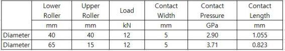
Operating Envelope – TE 74H(고하중 버전, 최대 하중 30kN)
Characteristic showing motor torque-speed characteristic (available torque) compared with roller generated torque, assuming traction coefficient of 0.1, with corresponding reduction in applied load. Note that the full load can be applied at full speed in pure rolling or under conditions where the traction coefficient is less than 0.08. 기본 샘플 롤러 70mm on 70mm 사용하고, 두개의 롤러 직경 최대 합이 140mm 이하 사용해야 함. 최대 차이는 30 on 110mm.
Assuming 70 mm diameter rollers and traction coefficient of 0.1, the maximum permissible load at maximum speed is 27.3 kN.
Flat Rollers 110 mm contact width
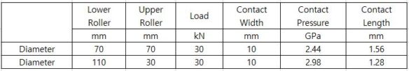
Flat Rollers5 mm contact width
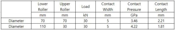
Crowned Rollers 4 GPa Contact Pressure
Note that as the minimum specimen diameter is 30 mm, a diameter of greater than this is required for a crowned roller sample machined on a 30 mm shaft. The practical minimum diameter for a crowned roller is thus 40 mm
Services:
Electricity: 380/415V, three phase plus neutral, 50/60 Hz, 75 kW
Clean, dry air: 4 cfm at 8 bar (120 psi)
Mains water and drain: 10 l/min (typical)

한미산업
1999년 개업 이후, 지난 30여년간
- Tribology(마찰/마모/윤활/CMP 연마), 스크래치, 고온 경도계, 베어링 시험기 : 미유럽 일본의 유명 제조공급사인 BRUKER, PHOENIX Tribology, TABER, SHINTO Heidon, INNOWEP, AMTEC, TRICO사.
- 열분석기(DSC,TGA,STA,TMA), 고온진공로 : 스위스 KEP 그룹의 SETARAM SETSAFE, 미국 MRF사, 일본 ENEOS MATERIALS사의 수지 열경화 시험기 등
최첨단 장비들을 국내에 소개 및 판매 기술 지원하여 왔으며, 또한 이기술을 바탕으로 일부 품목 제조를 통하여 국산화에도 노력하여 왔습니다. 앞으로도 더욱 노력하여 국내 기술 발전에 이바지 하도록 하겠습니다.
상호: 한미산업
대표: 최동하
사업자등록번호: 219-02-82992
Address
서울특별시 송파구 송파대로 167, 문정역 테라타워 A동 6층 619호. (문정동 651) 우편번호 05855
찾아오시는 길
서울 지하철 8호선 문정역 3번 출구에서 도보 약 300m 거리에 위치해 있으며, 지하 보행 통로로도 연결되어 있어 우천 시에도 편리하게 방문하실 수 있습니다.
Tel. 02-3411-0173
Fax. 02-3411-0178
choi.dongha77@gmail.com
견적문의
한미산업. All rights reserved.