
( 엉덩이, 고관절, 무릎—>인공 보철 장치에 대한 마찰력 측정기)
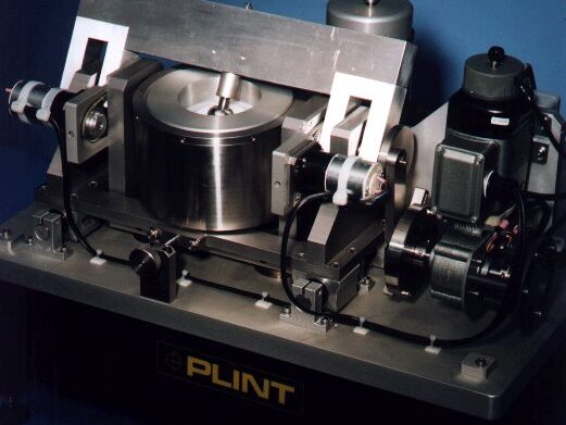
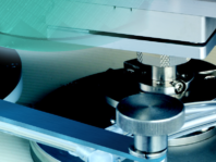
TE 89 Hip and Knee Joint Friction Simulator
모델 TE89 인체내 Hip,Knee 관절의 경계윤활 특성에 따른 마찰력/마찰계수 측정분석기—>
(점도 x 마찰속도) / 접촉압력)
변화에 따른 STRIBECK CURVE 특성 곡선 분석)
특징:인체공학전문가 Dr.Vessa Saikko(Helsinki University)와 기술 제휴하여 제작, UHMWPE(초고밀도 폴리에틸렌컵) 등의 재질에 대하여, 비구컵과(OR 정강이뼈 성장판) 대퇴부관절헤드의 실물로 마찰력(마찰계수)를 PIEOZ FORCE SENSOR로 매우 빠른속도 마찰력(마찰계수의) 변화를 측정 분석한다.
속도—> 0.02 to 1 Hz, 하중—> 200 to 2,500 N,
마찰력측정—>PIEZO FORCE SENSOR
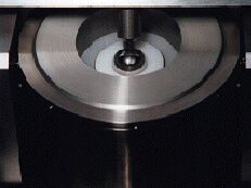
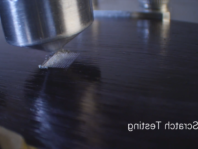
Close-up of Hip Joint Contact
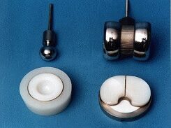
Hip and Knee Joint Specimens
Keywords: (시험분석 요소 )
- artificial joints (인공관절)
- compliant layers (유연재)
- friction coefficient (마찰계수)
- friction factor (마찰력 요소)
- hip prostheses (엉덩이 보철)
- knee prostheses (무릎 보철)
- mixed lubrication (혼합 윤활 영역)
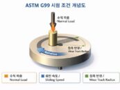
- stribeck curve (스트리벡커브->윤활유 특성 곡선, COF=마찰계수=(속도X점도)/접촉압력))
Background:
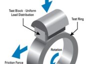
Artificial joints operate in the mixed lubrication regime, not with the full fluid films observed for natural human joints under physiological loading. As a result, artificial joints will experience higher friction and wear due to metal-plastic contact. Full fluid film lubrication is achieved in the natural joint as a result of the high degree of compliance of the joint surfaces. One way of improving the performance of the artificial joint is to introduce a more compliant surface.
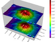
Measuring the joint friction and plotting the resulting Stribeck curve (the relationship between friction coefficient and the parameter velocity x viscosity x radius/load) is of fundamental interest in the design and development of better artificial joints.
Test machines have been developed at Durham University by Professor Tony Unsworth to study the frictional performance of hip and knee joint prostheses (see references at the end of this document). These machines operate with a simplified on/off loading cycle compared with physiological loading, in order to provide steady-state friction measurements during the loading phase for Stribeck analysis.
Plint & Partners Ltd have manufactured a modified version of the Durham Friction Simulators, with the agreement of Professor Unsworth. Comparative tests are being performed to ensure correlation with data generated on the original Durham machines.
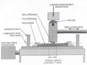
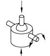
Description: The key performance requirements for the Friction Simulator are that it applies a defined load cycle in a predictable and repeatable fashion and measures the very low levels of friction generated within the lubricated joint.
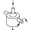
The machine comprises two support systems for the hip and knee joint components. Hip joints are inverted from their natural position. The acetabular cup or tibial plate component is mounted in a low friction trunnion mounted reservoir carried in a loading frame. The femoral component (either a taper mounted ball or special fixed axis knee piece) is mounted on the underside of a rigid cross-beam that is oscillated through an adjustable pre-set angle. A jig is provided to ensure that the femoral component is oscillated about its centre and is aligned with the lower test piece.
Load and Torque Measurement Assembly:
A high duty linear solenoid acting through a 9:1 lever applies the load to the carriage that supports the trunnion mounted reservoir. This system is compact, stiff and provides an easily controllable loading cycle. The load is measured by a piezo-electric force transducer mounted centrally on the carriage.
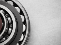
The trunnion bearings are mounted in such a way as to permit their inner races to be driven. Rotating the bearings increases their load carrying capacity from their static to their dynamic rating and reduces the parasitic friction from static to rolling friction. By driving the bearings in opposite directions the parasitic torque transmitted to the trunnion assembly by the bearings substantially cancels out. A parasitic torque of about 10% of the smallest measured friction torque is expected.
The trunnion mounted assembly is restrained from rotation by a piezo-electric force transducer carried on the lower loading carriage and connected by means of a flexure link.
Two reservoirs are provided, one for the acetabluar cup and one for the tibial plate. Tests may be run dry and lubricated with water, synthetic lubricants and synovial fluid.
Driven Component Assembly:
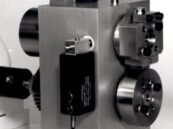
The cross beam carrying the femoral component is carried in bearings that are in line with the axis of the lower trunnion mounted assembly. These bearings are carried on brackets mounted on linear ball slides which allow the lower specimen assembly to be located correctly and locked in position.
The beam is oscillated sinusoidally through a crank mechanism with an adjustable throw. The mass of the arm and crank mechanism are minimised in order to minimise out of balance forces and thus to reduce the potential for parasitic excitation of other parts of the assembly. The drive arrangement comprises a thyristor controlled dc gear motor with tachogenerator feedback.
The timing between the load on/off action and the oscillating action is adjusted by means of an optical sensor and adjustable trigger. This permits the position of load and the duration of load application to be adjusted. It also permits the load to be applied on either the forward or reverse strokes.
Control and Data Acquisition:
The has PC based sequence programmable control and data acquisition. This is provided by an integrated Serial Link Interface Module and COMPEND 2000 software running on a host PC, operating under Windows. Data is stored to hard disc in standard spead sheet compatible file formats (.csv or .tsv).
Tests are defined by a sequence of steps, each step containing set-point, data recording rates and alarm level information. Set-points may be adjusted by step change or ramp. The test sequence is followed unless interrupted by the operator or an alarm. Set-points may also be adjusted manually using on screen toggles.
Specification:
Load Range: 200 to 2,500 N
Load Sensor: piezo-electric transducer
highest sensitivity: 10 mN
highest range: 7,500 N
Frequency Range : 0.02 to 1 Hz
Oscillating Angle: 0 to +/- 35 degrees
Friction Sensor: piezo-electric transducer
highest sensitivity: 1 mN
highest range: 500 N
Maximum Knee Size: 85 mm wide
Interface: PLINT SLIM 2000 Serial Link Interface Module
Software: PLINT COMPEND 2000 Windows based sequence control and data acquisition software
High Speed DAQ: PLINT SLIM 2000 Serial Link Interface Module
Total Memory: 640 kBytes
Sample Size: 2 Bytes per channel per sample
Number of Channels: 1 to 8
Data Rates: 75 Hz, 150 Hz, 300 Hz, 600 Hz, 1200 Hz
Controlled parameters
Applied Load
Rotational Speed (Frequency)
Number of Cycles
Test Duration
Recorded parameters
Applied Load
Rotational Speed (Frequency)
Frictional Torque
Number of Cycles
Test Duration
References:
Example publications on the original Durham Friction Simulators:
Frictional Properties of Artificial Hip Joints,
Unsworth A., Pearcy M. J., White E. F. T. and White G., Engineering in Medicine, 17 (30), 1988, 101-104.
Frictional Characterisation of Explanted Charnley Hip Prostheses,
Hall R. M., Unsworth A., Wroblewski B. M. and Burgess I. C., Wear, 175, 1994, 159-166.
Services:
Electricity:
220/240V, single phase, 50 Hz, 2.8 kW
110/120 V, single phase, 60 Hz, 2.8 kW
PC and Printer:
Minimum Specification
Installation:
Bench-mounting machine: 580 mm wide x 560 mm deep x 560 mm high
Bench-mounting cabinet: 540 mm wide x 540 mm deep x 450 mm high
Packing Specifications: 1.73 m3, GW 270 kg, NW 230 kg
Order As:
TE 89
Hip and Knee Joint Friction Simulator
USER LIST
Durham University
Stryker Howmedica Research, Ireland

한미산업
1999년 개업 이후, 지난 30여년간
- Tribology(마찰/마모/윤활/CMP 연마), 스크래치, 고온 경도계, 베어링 시험기 : 미유럽 일본의 유명 제조공급사인 BRUKER, PHOENIX Tribology, TABER, SHINTO Heidon, INNOWEP, AMTEC, TRICO사.
- 열분석기(DSC,TGA,STA,TMA), 고온진공로 : 스위스 KEP 그룹의 SETARAM SETSAFE, 미국 MRF사, 일본 ENEOS MATERIALS사의 수지 열경화 시험기 등
최첨단 장비들을 국내에 소개 및 판매 기술 지원하여 왔으며, 또한 이기술을 바탕으로 일부 품목 제조를 통하여 국산화에도 노력하여 왔습니다. 앞으로도 더욱 노력하여 국내 기술 발전에 이바지 하도록 하겠습니다.
상호: 한미산업
대표: 최동하
사업자등록번호: 219-02-82992
Address
서울특별시 송파구 송파대로 167, 문정역 테라타워 A동 6층 619호. (문정동 651) 우편번호 05855
찾아오시는 길
서울 지하철 8호선 문정역 3번 출구에서 도보 약 300m 거리에 위치해 있으며, 지하 보행 통로로도 연결되어 있어 우천 시에도 편리하게 방문하실 수 있습니다.
Tel. 02-3411-0173
Fax. 02-3411-0178
choi.dongha77@gmail.com
견적문의
한미산업. All rights reserved.